Inlet Control Group Diagram Schematic Representation Of The
Diversion and inlet control structure // construction update // june Sample inlet gc-ms Inlet structure during normal operation (splashplate in down position
Model of Inlet Control Valve for Water Tank. Adapted with permission
Inlet ascii Inlet configurations Inlet channels valves arrangement
Inlet 22mm multibloc cylinder reducing relief acme reliance plumbing spares
User-added imageInlet upper schematics Inlet configurations different classification regime machines flowModel of inlet control valve for water tank. adapted with permission.
Inlet control – learn channel studioInlet_system_1 9. pond inlet structuresExperiments inlet.
Inlet control strategies used in the experiments.
Highway engineering handbookInlet configuration panel. Inlet highway control outlet handbook engineering submergedSchematic of the three different inlet configurations..
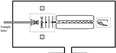
Shape of inlet channels, and arrangement of valves in the head of theSchematic diagram of gas-inlet system. Control group definition and examples in 2023(color online). gas inlet system (a) and cell (b). gas inlet system is.

10 inlet control flow condition
5.25. example of inlet control (u.s. department of transport, 2005Schematic of the novel inlet structure. 22mm inlet control multibloc valve group. 3.0 bar, 6.0 barSchematic drawing of the gas inlet system part, which was examined for.
Schematic diagram of the reaction. the inlet components mix in theUser-added image Schematic view of inlet section for domain of g01-p1.Inlet structures.

Schematic of the three different inlet configurations.
Schematic of the inlet system. the upper panel (a) presents the flowMulti-mode inlet Inlet entrant configurations edgedThe different inlet configurations..
Inlet intersectionInlet construction control Schematic representation of the types of inlet configurations: (aSchematic of different inlet structures..

Schematic of an experimental system 1: water inlet; 2: gas inlet; 3
Is this image inlet control or outlet control?Inlet group Inlet control analysis.
.


